ru
ru en
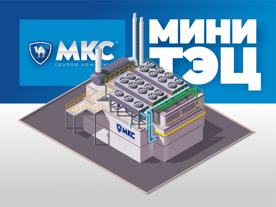
enMini-TEP (small thermal power center)
Table of contents
Mini combined heat and power (CHP) plants have a number of important advantages that make them attractive for businesses and residential complexes. First and foremost, they significantly reduce energy supply costs by placing the generating facility directly next to the consumer. This approach eliminates network losses and allows electricity and heat to be generated at cost, which is significantly cheaper than purchases from a guaranteed supplier. The economic effect in such projects is obvious: the payback period of mini CHP plants is usually achieved within three to five years. In addition, mini CHP plants contribute to increased energy independence of the consumer and allow flexible response to changes in energy prices.
From an environmental point of view, modern mini CHP plants use highly efficient gas piston units with low emissions, which reduces the negative impact on the environment. In addition, it is possible to integrate heat recovery systems and additional biomass-based fuel, making the facilities more environmentally friendly and energy efficient.
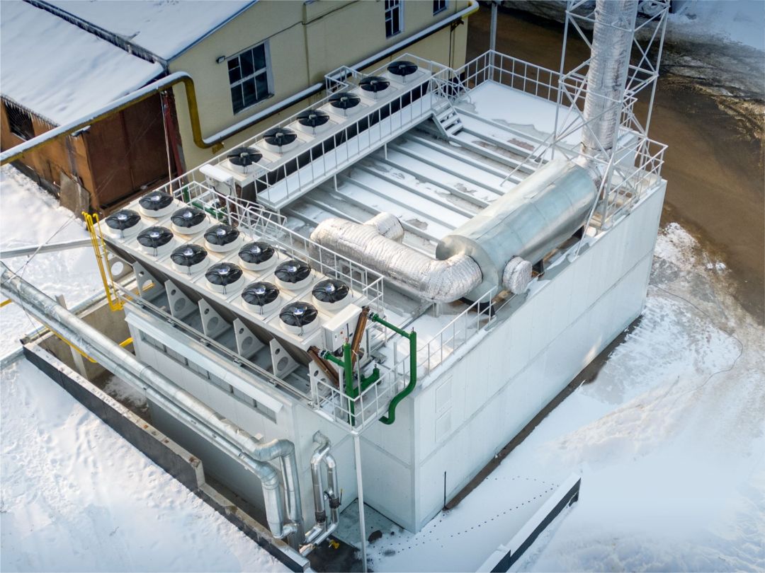
The advantages of proprietary block-modular solutions developed by the MKC Group of Companies are particularly important. Such blocks are fully ready for operation and undergo factory quality checks, which significantly reduces construction time and minimizes the risk of errors during installation. Block-modular mini CHP plants are mobile, easily transported, and can be quickly installed in conditions of limited space or on sites with difficult terrain. These solutions also provide a high degree of noise protection and vibration isolation, which is important when installing in populated or noise-sensitive areas.
Definition of Mini CHP
Mini CHP (decoding the abbreviation small combined heat and power plant) — is a compact power plant designed for the simultaneous production of electrical and thermal energy (cogeneration). The electrical capacity of mini CHP ranges from 100 kW to 25 MW (25,000 kW).
In Russia, their popularity is growing due to:
- Reduction of electricity and heat costs by 30-50% compared to network tariffs.
- High efficiency (up to 90%) due to cogeneration (joint production of electricity and heat). For comparison: separate sources, where electricity and heat are generated separately, have an efficiency of only 35-50%.
- Fuel flexibility (natural gas, biogas, synthesis gas, diesel).
- Legislative benefits (projects up to 25 MW are classified as "small power" under Federal Law No. 35-FZ, which simplifies the approval stages).
Main Purposes of a Small Combined Heat and Power Plant
1. Production of electricity. Power supply for industrial enterprises and cities.
2. Generation of heat (hot water/steam). Heating of residential areas, technological processes at factories.
3. Utilization of secondary energy resources. Use of heat from exhaust gases, cooling liquids, and waste, for example, mini CHP plants on wood waste.
4. Increasing energy efficiency. Reducing losses during energy transportation.
Principle Scheme of a Small Combined Heat and Power Plant
The main components of gas-piston mini CHP plants include the following elements:
- Gas piston engine
- Electric generator
- Heat exchangers
- Cleaning and ventilation systems
- Automated control system
- Fuel system
Equipment of the CHP plant and its purpose
Principle of Operation of a Small Combined Heat and Power Plant
Let's understand how a CHP plant works. Below is a sequential diagram of the operation of a mini CHP plant on natural gas:
1. Gas Supply and Preparation
The process begins with the gas system:
- Natural gas enters through the gas control station (GCS), where the pressure is reduced to working pressure (0.2-1.6 MPa)
- It undergoes filtration from mechanical impurities
- In the mixer, it is combined with air in an optimal ratio of 1:10
- The pressure is controlled by pressure gauges, and the composition of the mixture is controlled by gas analyzers
Typical consumption: 0.28-0.34 m³ of gas per 1 kWh of electricity
2. Operation of the Gas Piston Engine
Four strokes of the cycle:
2.1. Intake:
- Intake valves open
- The cylinder is filled with a fuel-air mixture
2.2. Compression:
- The piston moves upward
- The mixture is compressed to 10-15 bar
- The temperature reaches 400-500°C
2.3. Power Stroke:
- The spark plug ignites
- The temperature instantly rises to 1200-1400°C
- Pressure rises to 50-60 bar
- The piston receives a powerful downward push
2.4. Exhaust:
- Exhaust valves open
- Exhaust gases (400-600°C) exit into the exhaust manifold
- Shaft rotation speed: 750-1500 rpm
3. Electricity Generation
- Rotation of the crankshaft is transmitted to the synchronous generator
- The magnetic field of the rotor induces current in the stator windings
- The excitation system maintains stable voltage (400V-10.5kV)
- Automation synchronizes the frequency (50 Hz ±0.5%)
Efficiency of electricity generation is 95-98%
4. Heat Utilization
Heat is extracted from two sources:
4.1. Engine Cooling System:
- Antifreeze (80-110°C) circulates through the cooling jacket of the cylinder block and through the oil radiator
- In heat exchangers, it heats water for heating
4.2. Exhaust gases pass through a recovery boiler and produce:
- Hot water (90-110°C)
- Steam (up to 15 bar)
Power ratio: 1 MW electrical = 1.2-1.5 MW thermal
5. Emission Cleaning
Three-stage emission cleaning system:
1. Oxidation Catalyst. Burns CO and CH to CO₂ and H₂O with an efficiency of more than 90%
2. SCR System. Injects a urea solution (AdBlue) and converts NOx into harmless N₂ and H₂O
3. Industrial Muffler-Spark Arrestor:
- Reduces noise to 65-75 dB
- Captures solid particles
- Extinguishes sparks in high-temperature emissions
Emissions after cleaning:
NOx <100 mg/m³
CO <150 mg/m³
6. Automation and Control System (ACS)
Controls all parameters:
- Gas pressure
- Cooling liquid temperature
- Composition of exhaust gases
- Electrical parameters
In case of an emergency at the mini CHP plant, the automation system sends an alarm signal, shuts off the gas supply, and switches the system to safe mode.
Types of Fuel for Mini CHP Plants:
- Biogas — optimal for processing enterprises and agriculture, efficiency up to 85%.
- Associated Petroleum Gas (APG) — used in oil fields, requires preliminary desulfurization.
- Coal — used in regions with cheap coal and in enterprises where coal is a by-product in the production process. Efficiency is 10-15% lower than gas counterparts, has high emissions.
- Landfill gas — a type of biogas formed by the decomposition of organic waste in landfills.
- Mine gas — a by-product of coal mining, requires special preparation before use.
- Coke oven gas — a by-product of coke chemical production in metallurgy, characterized by a high hydrogen content.
- Liquefied gas (propane, LNG/LPG) — used in regions without centralized gas pipelines and requires regasification, i.e., the process of converting liquid fuel into a gaseous state, after which it becomes suitable for normal use. Special attention is required for liquefaction and pressurized storage.
- Purified gas — purified mine gas, petrochemical gases (after preparation), other industrial gases.
- Shale gas — extracted by hydraulic fracturing, requires complex preparation and purification.
- Biomethane — biogas purified to the quality of natural gas, suitable for use in standard gas engines.
- Peat gas — formed by the thermal decomposition of peat, used in regions with large peat reserves.
Example of a 5 MW Mini CHP Plant Operation
| Parameter | Value |
| Electrical Power | 5 MW |
| Thermal Power | 6 MW |
| Fuel | Natural Gas |
| Gas Consumption | 1100 m³/h (with a calorific value of 34.2 MJ/m³) |
| Inlet Pressure | 0.5 MPa |
| Network Water | 200 m³/h |
| Water Heating | from 70°C to 110°C |
| Emissions Before Cleaning | NOx 500 mg/m³ |
| Emissions After Cleaning | NOx 80 mg/m³ |
| Electrical Efficiency | 42% |
| Thermal Efficiency | 48% |
| Overall Efficiency | 90% |
| Nominal Load | 5 MW |
| Minimum Stable Load | 2.5 MW (50%) |
| Time to Reach Operating Mode | 15 minutes |
| Maintenance | Daily Inspection |
| Oil Change | Every 2000 hours |
| Major Overhaul | After 60,000 hours |
| Service Life of the Plant | 15-20 years |
Environmental Indicators of Mini CHP Plants
| Parameter | Value |
| CO₂ Emissions | 0.4 - 0.6 kg/kWh |
| NOx Emissions | 100 - 500 mg/m³ |
| Oxygen Content | 5-8% |
| Flue Gas Temperature | 400-600 °C |
Industrial mini CHP plants use cogeneration, which allows for the efficient use of heat generated during electricity generation. Typically, it is supplied as heated network water with a temperature of 90-105 °C, which is used for heating and hot water supply. For example, from 1 MW of electrical power, up to 1.5 MW of thermal power can be obtained.
Project Implementation Timelines
The construction timelines for mini CHP plants can vary from 2 weeks for block-modular designs to 2 years for full-scale construction, depending on the scale of the project. To date, the MKC Group of Companies has dozens of various facilities, and there has never been a one-size-fits-all solution. Each customer has their own characteristics, and to find out in advance about the commissioning timelines for mini CHP plants, contact us.
Technical Characteristics of Mini CHP Plants
| Parameter | Value |
| Electrical Power | 100 kW — 25 MW |
| Thermal Power | up to 30 MW |
| Efficiency of Electrical Part | 30-45% |
| Overall Efficiency (Electricity + Heat) | up to 90% |
| Type of Fuel | Natural Gas, Biogas, Synthesis Gas |
| Gas Pressure | 0.2 — 6.0 MPa |
| Exhaust Gas Temperature | 400 — 600 °C |
| Noise Level | 85 — 100 dB |
| Service Life | 60,000 — 120,000 hours |
| Maintenance Interval | 1,500 — 4,000 hours |
Technical Features
- Operating Resource: Some units can operate up to 60,000 hours before major overhaul.
- Power Regulation: Ability to regulate electrical power from 50 to 100%.
- Operational Characteristics: Gas piston units should operate at 70-80% of nominal power to compensate for load fluctuations.
Types of Combined Heat and Power Plants (Classification by Type of Power Plants)
1. Gas Piston Unit (GPU, English: Gas Engine CHP) — is a cogeneration unit where electricity is generated by a piston internal combustion engine running on gas, and heat is utilized from the cooling system and exhaust gases.
- Fuel: natural gas, biogas, synthesis gas.
- Power Range: 100 kW — 10 MW.
- Efficiency: up to 45% (electricity), up to 90% (with cogeneration).
2. Gas Turbine Unit (GTU, English: Gas Turbine CHP) — is a unit in which a gas turbine drives an electric generator, and heat is extracted from the exhaust gases (temperature up to 600°C).
- Fuel: natural gas, diesel, kerosene.
- Power Range: 1-300 MW (for mini CHP usually 1-25 MW).
- Efficiency: 25-38% (electricity), up to 85% (with cogeneration).
3. Microturbine Unit (MTU, English: Microturbine CHP) — is a small gas turbine equipped with a recuperator and often with a high-speed generator operating in the range of 50,000-120,000 rpm. In small distributed energy, this term is used to describe small gas turbines with low power.
- Fuel: gas, biogas, diesel.
- Power Range: 30-500 kW. Microturbines can be combined into a cluster — a single energy system that can collectively deliver up to 10 MW of power.
- Efficiency: 25-30% (electricity), up to 80% (with cogeneration).
4. Steam Turbine Unit (STU, English: Steam Turbine CHP) — is a unit where steam obtained in a boiler (by burning fuel or utilizing heat) drives a turbine connected to a generator.
- Fuel: coal, wood, waste, gas, fuel oil.
- Power Range: 1-100 MW (for mini CHP — up to 25 MW).
- Efficiency: 20-35% (electricity), up to 75% (with cogeneration).
Methods of converting fuel into electricity and heat (types of implementation of steam turbine mini CHP):
- Direct combustion (classic scheme) — fuel (coal, biomass, waste) is burned in a boiler, generating high-pressure steam that drives a steam turbine. Technological chain of direct fuel combustion in a steam turbine mini CHP: Fuel → Boiler → Steam → Turbine → Generator → Electricity + Heat
- ORC Unit (for low-potential heat) — uses an organic heat transfer fluid (freon, siloxane) instead of water, allowing operation at low temperatures (from 80° to 200°C). Technological chain of the ORC thermodynamic cycle in a steam turbine mini CHP: Heat source (90-200°C) → Evaporator → Organic steam → Turbine → Generator
5. Biomass/Coal Gasification Plant (English: Biomass/Coal Gasification CHP)
Definition: Thermochemical conversion of solid fuel into combustible gas (synthesis gas), which is then burned in a GPU/GTU.
- Fuel: wood, coal, peat, waste.
- Power Range: 0.5-10 MW.
- Efficiency: 30-40% (electricity), up to 85% (with cogeneration).
Additional Explanations
- ORC (Organic Rankine Cycle): Method of generating electricity using an organic heat transfer fluid (e.g., freon) instead of water. Used in steam turbine units for low-temperature heat sources (from 80°C).
- SCR (Selective Catalytic Reduction): System for reducing NOx emissions in exhaust gases (relevant for GPU/GTU).
| Type of Unit | Abbreviation | Fuel | Power | Electrical Efficiency |
| Gas Piston | GPU | Gas, Biogas | 0.1 - 10 MW | up to 45% |
| Gas Turbine | GTU | Gas, Liquid Fuel | 1 - 25 MW | 25 - 38% |
| Microturbine | MTU | Gas, Biogas | 30 - 500 MW | 25 - 30% |
| Steam Turbine | STU | Coal, Biomass | 1 - 25 MW | 20 - 35% |
| Gasification + GPU/GTU | _ | Coal, Wood | 0.5 - 10 MW | 30 - 40% |
All these types of equipment allow mini CHP plants to be flexible and efficient solutions for autonomous power supply.
Technologies for Reducing Harmful NOx/CO₂ Emissions
The MKC Group of Companies uses mini CHP plants based on gas piston units (GPU) using various technologies and cleaning systems to reduce emissions, such as:
1. Catalytic Neutralizers: These devices use catalysts to convert harmful substances such as nitrogen oxides (NOx) and hydrocarbons (CHx) into less harmful compounds (nitrogen N₂, water H₂O, CO₂).
2. Selective Catalytic Reduction (SCR) Systems: These systems inject ammonia (NH₃) or urea (AdBlue) into the exhaust gases to reduce NOx levels (converts to N₂ + H₂O).
3. Cyclone Filters: Used to remove solid particles (soot, ash) from exhaust gases.
4. Mufflers: They not only reduce noise levels but can also be equipped with additional exhaust gas cleaning systems (e.g., CO/CHx afterburners).
5. Electrostatic Filters: Used to capture fine particles (PM2.5, PM10) and aerosols.
Thanks to all these innovative technologies, gas piston engines will be the most environmentally friendly solution among this equipment, especially compared to traditional fossil fuels.
Differences Between Mini CHP and Mini Power Plants
Mini CHP and mini power plants are often used as synonyms, but there are significant differences:
| Parameter | Mini CHP | Mini Power Plant |
| Heat Production | Yes (cogeneration) | Absent (only electricity) |
| System Efficiency | Up to 90% (heat + electricity) | 30-45% (heat loss) |
| Payback Period | 3-7 years | 5-10 years |
| Main Fuel | Gas, Diesel, Biogas | Gas, Diesel, Coal |
| Application | Factories, Housing and Utilities, Shopping Centers, Hospitals | Remote facilities without heat consumption |
Differences Between Mini CHP and CHP
| Parameter | Mini CHP | CHP |
| Power | 100 kW - 25 MW | 50 MW and more |
| Fuel | Natural Gas, Biogas, Synthesis Gas | Natural Gas, Coal, Fuel Oil, Biomass |
| Overall System Efficiency | Up to 90% | Up to 85% |
| Purpose | Local Power Supply and Heating | Power Supply and Centralized Heating |
| Dimensions and Weight | Compact, Modular Designs | Large Stationary Units |
| Construction Timelines | 3 - 12 months | 2 - 5 years |
| Personnel Requirements | Minimal (automated systems) | High Requirements, Complex Systems |
| Cost | Significantly lower than CHP | High |
| Environmental Friendliness | High Environmental Friendliness | The higher the power, the lower the environmental friendliness |
| Flexibility | High, Quick Adaptation to Load | Limited Flexibility |
For capacities above 25 MW, different regulations are required, so most industrial projects fit within this limit.
Stages of Mini CHP Project Implementation
- Analysis of energy needs
- Selection of fuel type
- Development of a technical project
- Coordination with gas supply authorities
- Site preparation
- Equipment installation
- Connection to utility networks
3. Commissioning:
- System testing
- Equipment setup
- Regular maintenance
- System performance monitoring
Example of Mini CHP Power Calculation
Let's ensure the power supply for an enterprise with a consumption of 5 MW of electricity and 4 MW of thermal energy.
- Electrical Power: 5 MW
- Thermal Power: 4 MW
- Electrical Efficiency: 40%
- Overall System Efficiency (electricity + heat): 85%
Effective Power:
P_eff = (P_el + P_thermal) / Overall Efficiency = (5 + 4) / 0.85 = 10.6 MW
That is, to meet these needs, a mini CHP plant with a capacity of at least 10.6 MW is required.
Fuel Consumption Calculation
The specific gas consumption is calculated using the formula:
G = (P_el + P_thermal) / (η * Q)
where:
G — gas consumption (m³/h)
P_el — electrical power (MW)
P_thermal — thermal power (MW)
η — overall efficiency
Q — calorific value of gas (34.2 MJ/m³)
For example: G = (5 + 4) / (0.85 * 34.2) = 0.307 m³/s ≈ 1100 m³/h
Economic Calculation of Mini CHP
Main costs include:
- Equipment cost
- Installation and commissioning
- Fuel cost
- Operational expenses
The payback period of a mini CHP plant can be calculated using the formula:
T_payback = C_capital / (R_annual - E_operational)
where:
T_payback — payback period (years)
C_capital — capital costs
R_annual — annual revenue from electricity sales
E_operational — annual operational expenses
Example:
Capital Costs: 150 million rubles
Annual Savings: 50 million rubles
Operational Expenses: 20 million rubles
Calculation: T_payback = 150 / (50 - 20) = 5 years
Application of Mini CHP in Various Industries
| Industry | Example of Application | Power |
| Industry | Cogeneration for Plants and Factories | 5-25 MW |
| Housing and Utilities | Heating of Residential Complexes and Districts | 1-10 MW |
| Agriculture | Greenhouses, Livestock Complexes | 0.5-5 MW |
| Meat Processing Plants | Waste Processing | 5-25 MW |
| Medical Institutions | Autonomous Power Supply | 1-3 MW |
| Chemical Industry | Steam for Technological Processes | 5-25 MW |
Fuel for Mini CHP Plants:
Biogas — optimal for processing enterprises and agriculture, efficiency up to 85%.
Associated Petroleum Gas (APG) — used in oil fields, requires preliminary desulfurization.
Coal — used in regions with cheap coal and in enterprises where coal is a by-product in the production process. Efficiency is 10-15% lower than gas counterparts, has high emissions.
Landfill Gas — a type of biogas formed by the decomposition of organic waste in landfills.
Mine Gas — a by-product of coal mining, requires special preparation before use.
Coke Oven Gas — a by-product of coke chemical production in metallurgy, characterized by a high hydrogen content.
Liquefied Gas (propane, LNG/LPG) — used in regions without centralized gas pipelines and requires regasification, i.e., the process of converting liquid fuel into a gaseous state, after which it becomes suitable for normal use. Special attention is required for liquefaction and pressurized storage.
Purified Gas — purified mine gas, petrochemical gases (after preparation), other industrial gases.
Shale Gas — extracted by hydraulic fracturing, requires complex preparation and purification.
Biomethane — biogas purified to the quality of natural gas, suitable for use in standard gas engines.
Peat Gas — formed by the thermal decomposition of peat, used in regions with large peat reserves.
More about LNG and LPG:
1. LNG (Liquefied Natural Gas)
Composition: 90-99% methane (CH₄)
How it is obtained: Cooling natural gas to -162°C (conversion to liquid state, volume reduced by 600 times)
Use in Mini CHP Plants:
- Requires regasification of liquefied natural gas — the process of converting LNG from liquid to gaseous state, after which it becomes suitable for normal use — supply through pipelines to consumers and filling into gas cylinders.
- Pressure: 4-8 bar
- Clean fuel (minimum impurities)
2. LPG (Liquefied Petroleum Gas)
Composition: Propane (C₃H₈), butane (C₄H₁₀) or their mixture
How it is obtained: Liquefaction at room temperature under pressure
Use in Mini CHP Plants:
- More often used in cylinders for remote facilities
- Requires an evaporator (for conversion to gas)
- Higher energy content than natural gas
Key Differences Between LNG and LPG:
| Parameter | LNG | LPG |
| Main Component | Methane (CH₄) | Propane-Butane |
| Storage Temperature | -162°C | +20°C (under pressure) |
| Application Area | Large CHP Plants, Ships | Autonomous Systems |
Additional Recommendations:
For mini CHP plants, LNG is preferable if high power is needed.
LPG is convenient for temporary facilities (e.g., construction sites).
Clarify with the GPU manufacturer (e.g., MWM) the permissible gas parameters.
For all gases (except natural gas), individual calculation is required:
- By calorific value
- By composition of impurities
- By supply pressure
Technical Nuances for Extractive Industries:
· For mining and gold mining:
- Protected design of equipment is required (dust/moisture protection IP54)
- Ability to operate in autonomous mode (disconnection from networks)
· For the oil and gas sector:
- Use of associated gas with preliminary purification (liquid separation, H₂S removal)
- Mobile solutions on chassis for temporary fields
· For meat processing:
- Utilization of blood meal and fats as fuel (additional savings)
- Deodorization systems for emissions (catalytic reactors)
Example calculation for a gold mining enterprise:
Consumption: 4 MW (electric) + 3 MW (heat for workshop heating)
Fuel: diesel (backup) + gas (main)
Power Calculation: P_eff = 4 + 3 / 0.82 = 8.5 MW → We choose 2 × GPU of 4.5 MW
Payback Period: 4-5 years (due to high network tariffs in remote areas)
5.1. Scheme of Mini CHP Integration at a Mining Enterprise
Gas Pipeline/Diesel → Mini CHP → Electricity (↓)
↑
Heat Exchanger → Process Heat
↓
Heat Utilization (Heating)
5.2. Regulations for Hazardous Productions
- Rostechnadzor Requirements for Oil and Gas Facilities (Federal Norms and Rules No. 542)
- Penalties for Emissions (in case of exceeding MPE): up to 500 thousand rubles/month.
Advantages of Mini CHP Plants
Compared to traditional industrial plants and centralized power grids, mini CHP plants have a number of significant advantages:
1. Energy Efficiency:
Mini CHP plants use the principle of cogeneration, which allows for the simultaneous production of electricity and heat with an efficiency of up to 80-90%. Unlike traditional power plants, where a significant portion of energy is lost as heat, mini CHP plants use this heat for heating or technological needs, significantly increasing overall efficiency.
2. Reduction in Energy Costs:
Unlike centralized networks, where consumers pay for the transmission of energy over long distances, mini CHP plants allow for reducing energy costs through local production. This is especially important for enterprises with high energy consumption.
3. Autonomy and Reliability:
Mini CHP plants provide energy independence for facilities, which is especially important for remote regions or facilities with unreliable centralized power supply. Unlike traditional networks, mini CHP plants can operate autonomously, reducing the risk of power supply interruptions.
4. Environmental Safety:
Compared to coal-fired power plants, mini CHP plants have lower emissions of harmful substances. The use of modern technologies and fuels (e.g., natural gas or biogas) allows minimizing the environmental footprint.
5. Flexibility in Placement:
Mini CHP plants can be installed in close proximity to the consumer, reducing energy transmission losses. Unlike large industrial plants that require significant space and infrastructure, mini CHP plants can be placed on the enterprise's premises.
6. Modularity and Scalability:
Unlike traditional power plants that require significant investments and construction time, mini CHP plants can be easily scaled depending on the customer's needs. This allows for gradually increasing the capacity of the plant as energy consumption grows.
7. Use of Various Types of Fuel:
Mini CHP plants can operate on various types of fuel, including natural gas, biogas, diesel fuel, and others, providing flexibility in the choice of energy resources. Unlike traditional networks that often depend on one type of fuel, mini CHP plants can adapt to available resources.
8. Reduction in Load on the Power System:
Local energy production reduces the load on centralized power systems, which is especially important during peak consumption periods. Unlike traditional networks that can experience overloads, mini CHP plants provide stable power supply.
9. Economic Benefit:
The implementation of mini CHP plants can lead to significant savings on energy costs, positively affecting the financial performance of the enterprise. Compared to traditional networks where energy tariffs can be high, mini CHP plants allow for controlling energy costs.
10. Support for Renewable Energy Sources:
Mini CHP plants can be integrated with renewable energy sources such as solar panels or wind turbines, allowing for the creation of hybrid energy systems. Unlike traditional networks that often depend on fossil fuels, mini CHP plants can use renewable resources.
Mini CHP plants represent an efficient and economically beneficial solution for providing energy to industrial enterprises.
Conclusion
For extractive and processing industries, mini CHP plants up to 25 MW are:
- Reduction of dependence on network tariffs in remote areas
- Utilization of associated resources (biogas, coal dust, APG)
- Payback period of 3-7 years even when operating on diesel and 2-4 years when operating a mini CHP plant based on a gas piston unit.
© MKC Group of Companies LLC, 2025
Need a consultation? Apply for it!
Other publications