ru
ru en
enCogeneration. What it is?
Table of contents
Cogeneration is a technology to simultaneously produce electric and thermal energy, used in the electric power industry. The main premise in the cogeneration development is the fact that the process of electric energy generation provided the technical possibility to use remove associated heat.
Today, this process is the most economical way to generate energy resources, increasing the overall efficiency of cogeneration plants up to 90%. In Russia and abroad, cogeneration is used in up-to-date energy systems, at urban thermal power plants which provide centralized electricity and heat supply to many consumers.
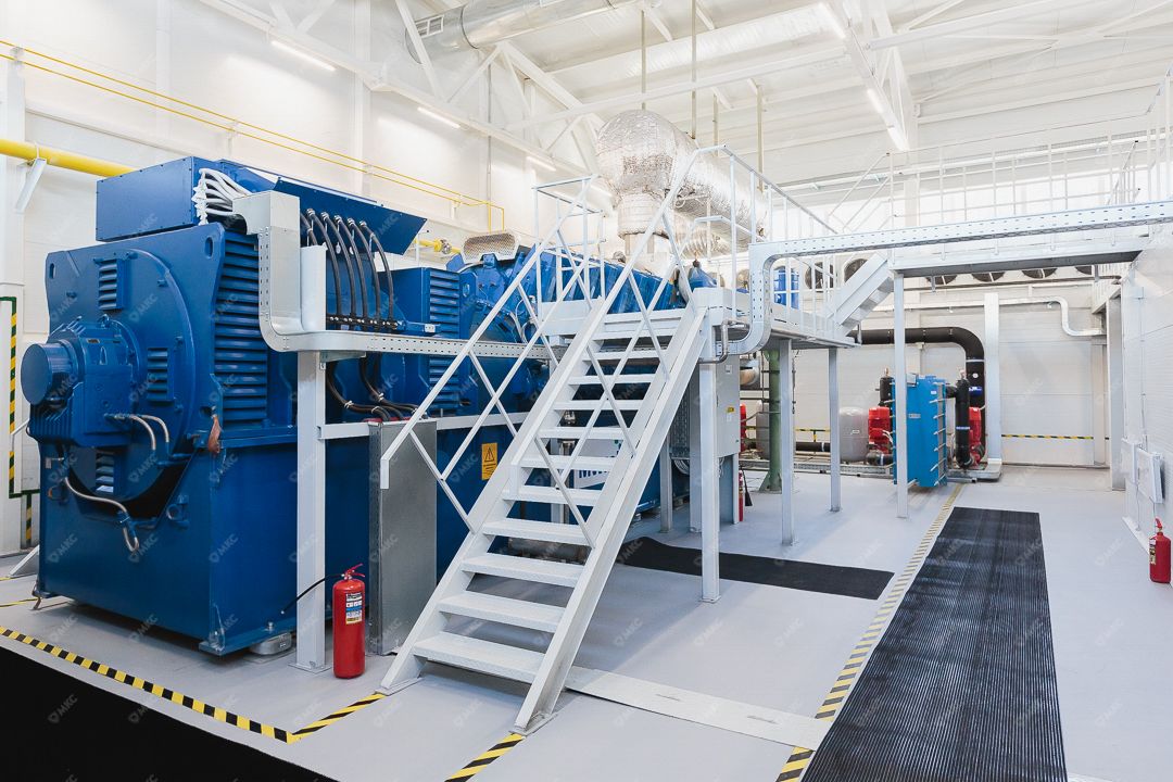
Cogeneration plant (CHP)
Cogeneration plants (CHPs) are also actively used in the field of the small-scale distributed generation (mini-CHP, mini-thermal power plants) in local power systems. Such development is due to several factors, the main ones being the proximity of generating plants to consumers, independence from external energy supplies, and increased reliability of energy supply. In small-scale distributed energy, cogeneration plants based on gas piston engines and gas turbine units have become the most widespread.
The principle of operation of cogeneration plants
Depending on the operating principle, there are several types of cogeneration plants.
Let's consider a CHP based on gas piston units. The combustible gas of the required parameters is supplied to the gas engine. In the process of burning fuel, mechanical energy is generated, transmitted through a single shaft to the generator and converted into electrical energy of standard quality parameters.
A large amount of heat, which can be utilized with special equipment and then used is released when the internal combustion engine of a gas power plant operates. At the same time, no additional fuel is used to obtain this energy - this product is a coproduct of the technological process of electric power generation. The main sources of associated heat during operation of the gas reciprocating unit:
- heat of the cooling water (engine cooling jacket);
- the heat of the exhaust gases.
These sources can be used to produce heat energy (heat utilization), thus regulating the temperature and the amount of energy resource produced, as well as the amount of auxiliary equipment to be installed.
The system of heat utilization from cogeneration plants allows to obtain associated heat energy of required parameters with the help of heat exchangers and utilization boilers, removing heat from heated parts and mediums. The generated heat energy is supplied to the existing heat supply system of the enterprise. If the associated heat of gas piston installations is not used, thermal energy is discharged into the atmosphere.
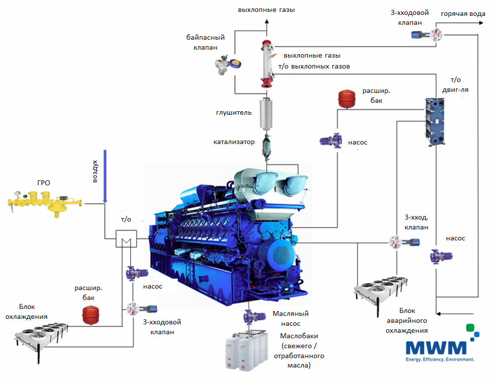
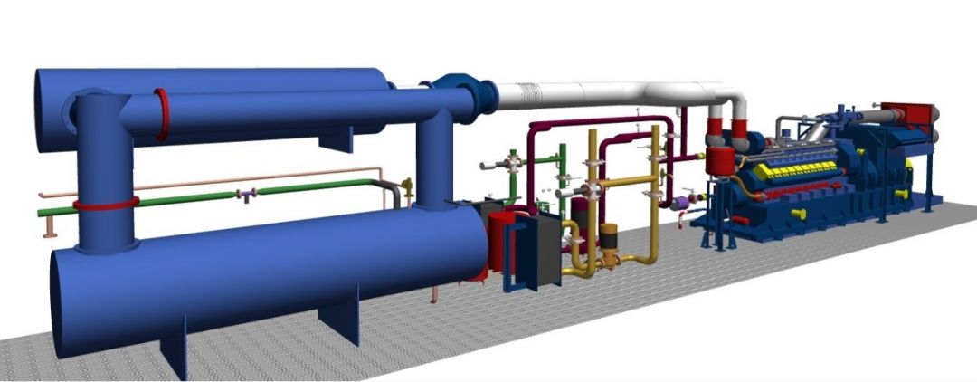
The schematic diagram of the technological process of heat recovery from MWM gas piston units is shown in the figure below.
The thermal (heat) efficiency of gas-piston units is approximately at the same level as the electrical one, providing practically the same output parameters in terms of electrical and thermal power, regardless of whether a cogeneration unit of small, medium or large capacity is considered.
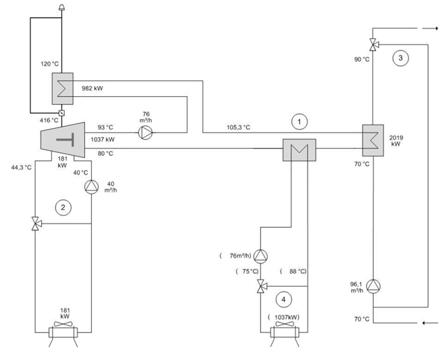
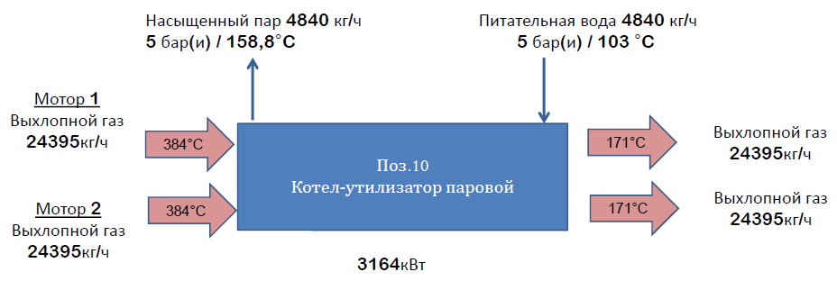
The operation of the heat recovery system of the gas plant is organized by several thermal circuits. An enlarged diagram of the technological process of the gas piston installation circuits with a nominal electrical capacity of 2000 kW to ensure heat recovery from heat exchangers and heat recovery boilers is shown in the figure below.
The process flow diagram shown here reflects the hydraulic connection of the MWM gas piston unit only.
The following contours are indicated in the figure:
- engine cooling contour;
- mixture cooling contour;
- heating contour;
- emergency cooling contour (system).
The above process diagram shows just the hydraulic connection of the MWM gas piston unit.
The water temperature at the outlet of the CHP heat recovery system is 90 °C, at the inlet the water comes with a temperature of 70 ° C. During operation of the CHP, 50% of the heat is obtained by cooling the engine using ethylene glycol/water heat exchangers, while the coolant is heated at 10 ° C (from 70 ° C to 80 ° C). The remaining 50% of the heat is produced by cooling the exhaust flue gases from 500 ° C to 120 ° C on the recovery boiler. The heat-storage medium is heated by another 10 ° C (from 80 ° C to 90 ° C).
During the operation of the gas reciprocating unit installation, the generation of electric energy is a priority task of the CHP. The generation of thermal energy is proportional to the degree of utilization of the machine (the amount of electricity generated). Russian-made cogeneration plants are less common in the small-scale distributed energy market but have a similar operating principle and conditions.
Engineering solutions
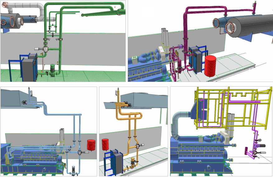
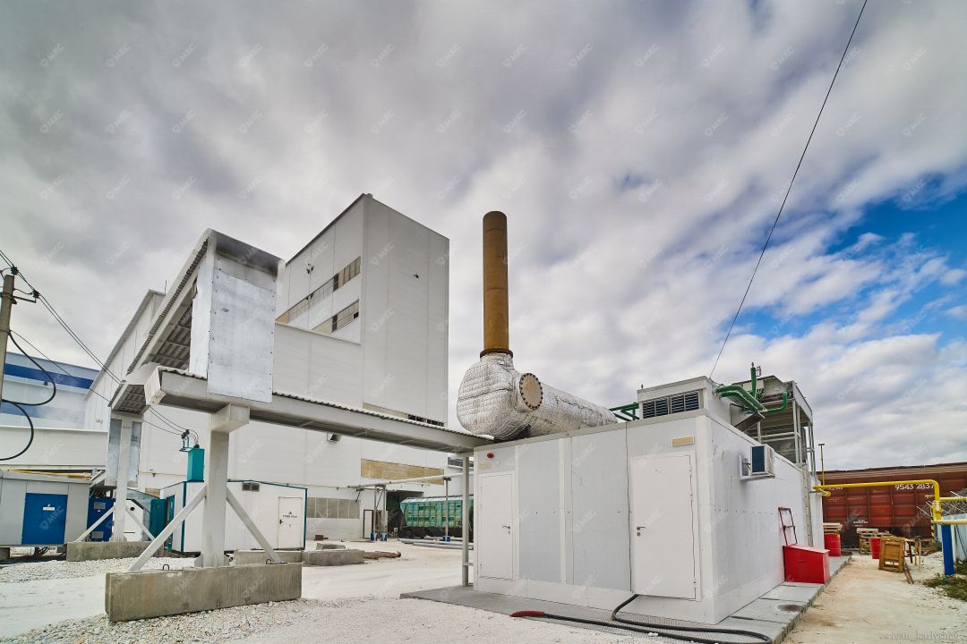
During the design process, a complete calculation of the cogeneration plant, all its parameters, operating modes, characteristics and conditions is carried out. The emergency cooling contours of the engine and the cooling of the fuel mixture of heat recovery systems include air coolers, usually located on the roof of the gas piston unit container.
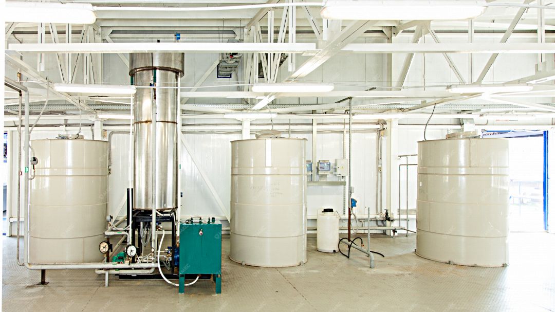
In order to prevent defrosting of pipelines and air coolers, which would inevitably lead to their failure, it is necessary to use ethylene glycol solution as a coolant (according to the recommendations of the MWM CHP manufacturer). The coolant in the circuits with the solution should be replaced once a year. Ethylene glycol is delivered by truck hauling in 200-liter barrels.
Compensation for thermal expansion of the coolant is provided by installing expansion tanks in each circuit of the CHP. It is planned to latch armature to disconnect the tanks from the system and empty them during maintenance.
A drainage system with organized collection (from the main, heat-exchange, auxiliary equipment, cut-off sections of pipelines) is provided for equipment and pipelines with coolant. The emergency discharge of the coolant is carried out in special containers, followed by discharge into an intermediate cooling well, followed by discharge into the household. domestic sewerage.
To prevent reverse circulation, flanged check valves are provided in the heating circuits of the CHP heat recovery system. Adjustable clutch safety valves are installed to protect the heating contour equipment from increased mains water pressure. At the upper points, the pipelines are equipped with manual air vents, at the lower points with descenders. Pressure and temperature sensors, as well as indicating pressure gauges and thermometers, are installed on pipelines to ensure automatic control and visual control.
To ensure the normative level of heat losses of pipelines and the temperature of their external surfaces safe for humans, thermal insulation structures are provided.
Operation
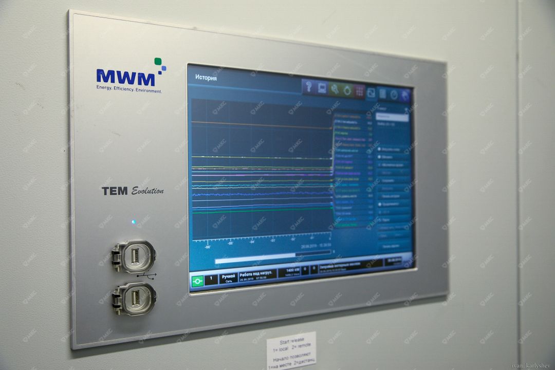
To control and monitor the operation of the gas piston cogeneration unit, control cabinets are installed. These cabinets are installed in the immediate vicinity of the unit itself. The location of the control device (control computer) can be selected depending on the customer's wishes: both on the unit and on the control panel.
The control system performs a certain set of basic functions necessary for the safe and efficient operation of the cogeneration plant: monitoring of all parameters, control of the main systems, actuators, switching and shut-off control equipment.
The advanced functions of the control system are related to the operation of the heat recovery system but not limited to the following:
- heat recovery in the heating circuit: expansion of the safety contour to control the heating contour and adjustment of the inlet temperature of the cooling water of the engine, as well as the supply line of the heating contour by controlling a three-way valve in the heating contour. Measuring the temperature of supply and return lines, heating water before the cooling water heat exchanger, controlling the temperature of flue gases after the flue gas heat exchanger. The heating circuit control ensures that the heating water temperature in the supply line is stable even at partial engine load, while at the same time ensuring that the engine's cooling water temperature requirements are met;
- monitoring of the exhaust gas temperature after the engine and after the catalyst;
- control of the emergency cooling and exhaust bypass system;
- control of the cooler of the mixture cooling and engine cooling circuits or the emergency cooling system.
Station operation mode
During the operation of the gas reciprocating unit installation, the generation of electric energy is a priority task of the CHP. The generation of thermal energy is proportional to the degree of utilization of the machine (the amount of electricity generated). When the thermal capacity produced by the power plant exceeds the consumption capacity, the unused or excessive part of the associated heat from the gas piston units is discharged into the atmosphere. In the opposite situation, when there is a shortage of heat utilized from the gas engine plant, when the required electrical load is less than the heat load, the heat shortage problem is solved by installing additional hot-water or steam boilers in parallel with the CHP heat recovery system.
The cogeneration mode is the most economically feasible way to generate energy resources, increasing the overall efficiency of cogeneration plants by over 90%.
Types of CHP cogeneration
The heat recovery system of gas-piston power plants allows you to remove associated heat from a running engine using heat exchangers and heat recovery boilers.
The system allows you to obtain the thermal energy of the required parameters:
- hot water, standard temperature schedule of 90/70 °C (hot water heat exchangers and heat recovery boilers). If necessary, the parameters can be increased using peak boilers;
- saturated steam of standard parameters (steam recovery boilers).
If necessary, the steam can be superheated using superheaters.
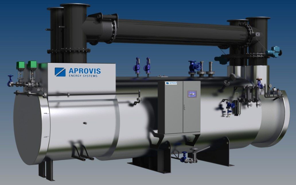
The most widespread are water-heat recovery systems of cogeneration plants - these are the simplest and optimal solutions based on the use of plate heat exchangers and heat-recovery steam generator (HRSGs) heating network water.
However, the development of small-scale distributed generation technologies allowed to develop and use steam heat recovery systems - a system of steam production of required parameters based on heat-recovery steam generator (HRSGs) due to utilization of high-potential heat of flue gases exhausted from SRBs. It is also possible to organize mixed-type recycling systems, when using a set of certain equipment, both standard hot water and saturated steam can be obtained. In this case, it is optimal to use high-power gas piston installations, or use several CHP with a different set of heat removal equipment. Solutions for usage of a steam heat recovery system in a gas piston installation are listed below.
Trigeneration
In addition to the cogeneration mode with simultaneous generation of two energy resources, it is possible to organize a trigeneration mode on a gas piston installation using specially installed equipment – simultaneous generation of three energy resources – electricity, heat and cold.
The trigeneration plants are cost-effective in the sector of small-scale distributed generation, because they allow using heat disposed from gas genset units not only in winter, for heating purposes, but also in summer, for room conditioning or cooling for process needs.
This increases the overall efficiency of the installation, which may be used in such conditions all the year round keeping high efficiency.

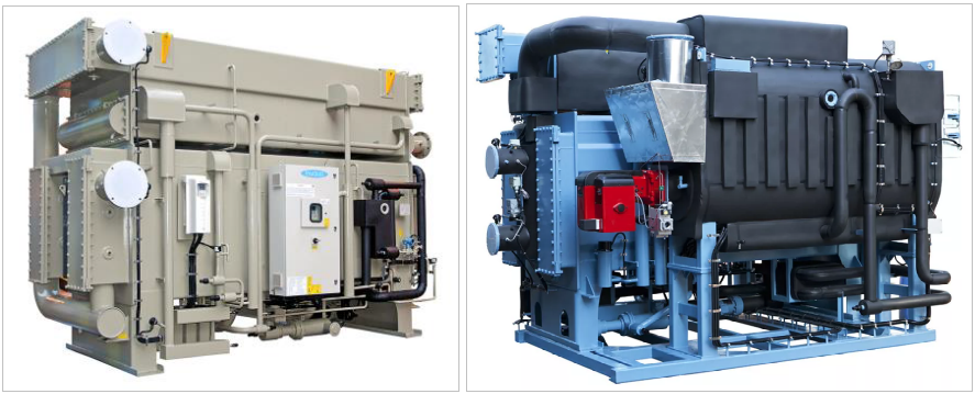
For trigeneration purposes, absorption lithium bromide refrigeration units (ABHM) are used - a refrigeration unit designed for extraction and removal of excess heat from thermal units and maintenance of a given optimum temperature and thermal regime. They use various solutions as an absorbent. Part of the heat utilized from the gas-fired plant is fed to the ARS to generate refrigeration. Cold can be used for cooling water as well as in air conditioning systems, or for technological needs.
Fuel
MWM gas cogeneration plants operate on various types of combustible gaseous fuels.
The most common and efficient type of fuel is natural gas. Other possible types of gaseous fuels:
- landfill gas;
- biogas;
- associated petroleum gas;
- mine gas;
- purification gas;
- coal mine gas;
- coke oven gas;
- liquid gas (propane, LNG), etc.
When using alternative types of gaseous fuels, a preliminary gas analysis and verification of the composition and parameters of the gas for compliance with the requirements of the manufacturer are required.
Equipment
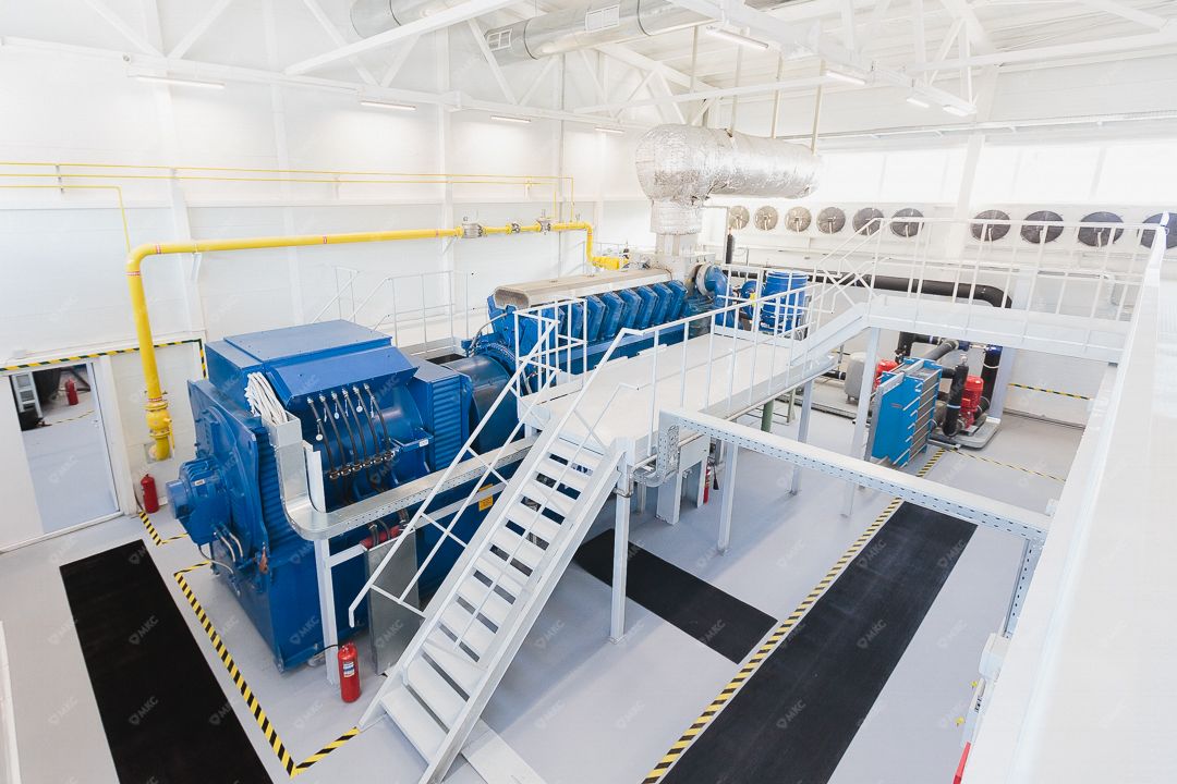
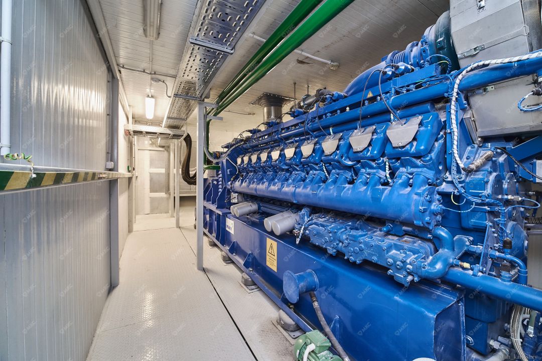
The "heart" of a gas piston cogeneration power plant is an MWM gas engine connected on one shaft and mounted on the same frame with an alternating current generator.
The plant is equipped with the associated equipment required for normal operation.
The range of MWM gas piston units with an indication of the main technical characteristics can be viewed on our website in the "Equipment" section.
There are also other manufacturers of cogeneration plants on the market: caterpillar, viessmann, jenbacher, cat, man etc.
The equipment of the heat recovery system (thermal module) for the gas piston cogeneration plant is supplied complete with KGU. The location of the auxiliary equipment is provided in such a way as to ensure the safe performance of work during maintenance, repair and replacement.
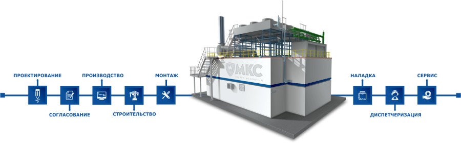
Implementation of cogeneration projects
When implementing an in-house generation facility, the focus is on quality and a range of services, therefore, as a rule, such projects are implemented by engineering companies that perform the whole range of turnkey works - from design and survey works to facility start-up and maintenance.
The diagram shows an enlarged flowchart of the work on the construction of a turnkey facility of its own generation by one of the leaders in launching such facilities in the country based on gas piston installations, the MKS Group. Each stage of this technological chain is very important, each stage is not possible without others and requires the highest competence of the performers. If all the work is done by one turnkey company, so obviously the final cost of such an object will be lower than if each stage was performed by different contractors. Also, a single contractor will control the quality of work at each stage, which cannot be said about several contractors, where each is responsible only for his specific volume, and not for the project.
Advantages of cogeneration (trigeneration)
Cogeneration (trigeneration) projects have several advantages. The main ones are as follows:
- simultaneous generation of several useful energy resources – electric energy, heat, cold when burning the same amount of fuel;
- maximum overall plant efficiency (up to 90%);
- low cost of electricity production in the cogeneration (trigeneration) mode;
- optimal cost of cogeneration plants;
- a wide range of rated capacities of CHP;
- long service intervals and maximum time to overhaul among units of its class;
- portability, possibility of block-modular design;
- environmental friendliness and safety meeting European standards;
- optimum flow and operation costs;
- quick project payback.
Economics and efficiency of cogeneration (trigeneration)
Cogeneration plants increase efficiency for the customer's company in terms of its energy supply system. The main economic effect of using KSU is to obtain associated conditionally free energy resources (heat, cold) without additional fuel costs. This effect leads to a noticeable reduction in the cost of electricity generation relative to the monogeneration mode (electricity generation only), when all costs are allocated to only one resource. As a result of cogeneration, the consumer receives all the generated resources much cheaper than from centralized networks.
Also, a significant criteria towards cogeneration is the placement of the generating facility in close proximity to the consumer – this reduces transmission losses and eliminates the presence of a transport component in the cost of energy resources.
In this connection, projects of realization of gas-piston cogeneration power plants now have rather attractive payback period for the enterprise-consumer - up to 5 years.
At the same time, the deadlines for the implementation of such projects are usually within one calendar year, which makes projects of cogeneration (trigeneration) installations not only affordable, but also an obviously profitable and logical step.
The issue of the cost of implementing cogeneration
The issue of the cost of implementing cogeneration and trigeneration projects always remains one of the main ones. According to the average estimates of engineering companies organizing the implementation of mini-HPP projects, the approximate unit cost of turnkey construction of such a facility in the cogeneration mode is about 650 euros per 1 kW of installed electric capacity. If the project is complicated up to trigeneration mode, the preliminary unit cost can be up to 750-800 euros per 1 kW of installed electric capacity and higher, depending on the complexity and volume of equipment. These rates are competitive in terms of obtaining the above-mentioned advantages, and competent businessmen understand this.
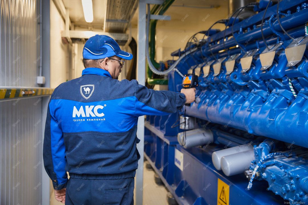
The MKS Group is a leading engineering company in Russia, the main activity of which is the construction of small–scale energy facilities - turnkey gas piston power plants. In 14 years, it has commissioned 53 CHP-plant in various regions and abroad. The total capacity of all commissioned facilities of the MKS Group was 244 MW. The MKS Group is the official Russian dealer and service partner of MWM Austria GmbH.
© MKC Group of Companies LLC, 2020
Need a consultation? Apply for it!
Other publications